Pinouts (M12 & Terminal)
This page provides complete pinout details for the OV20i smart camera’s connectors, including the 17-pin M12 Power & I/O interface and the M12 X-coded Ethernet port.
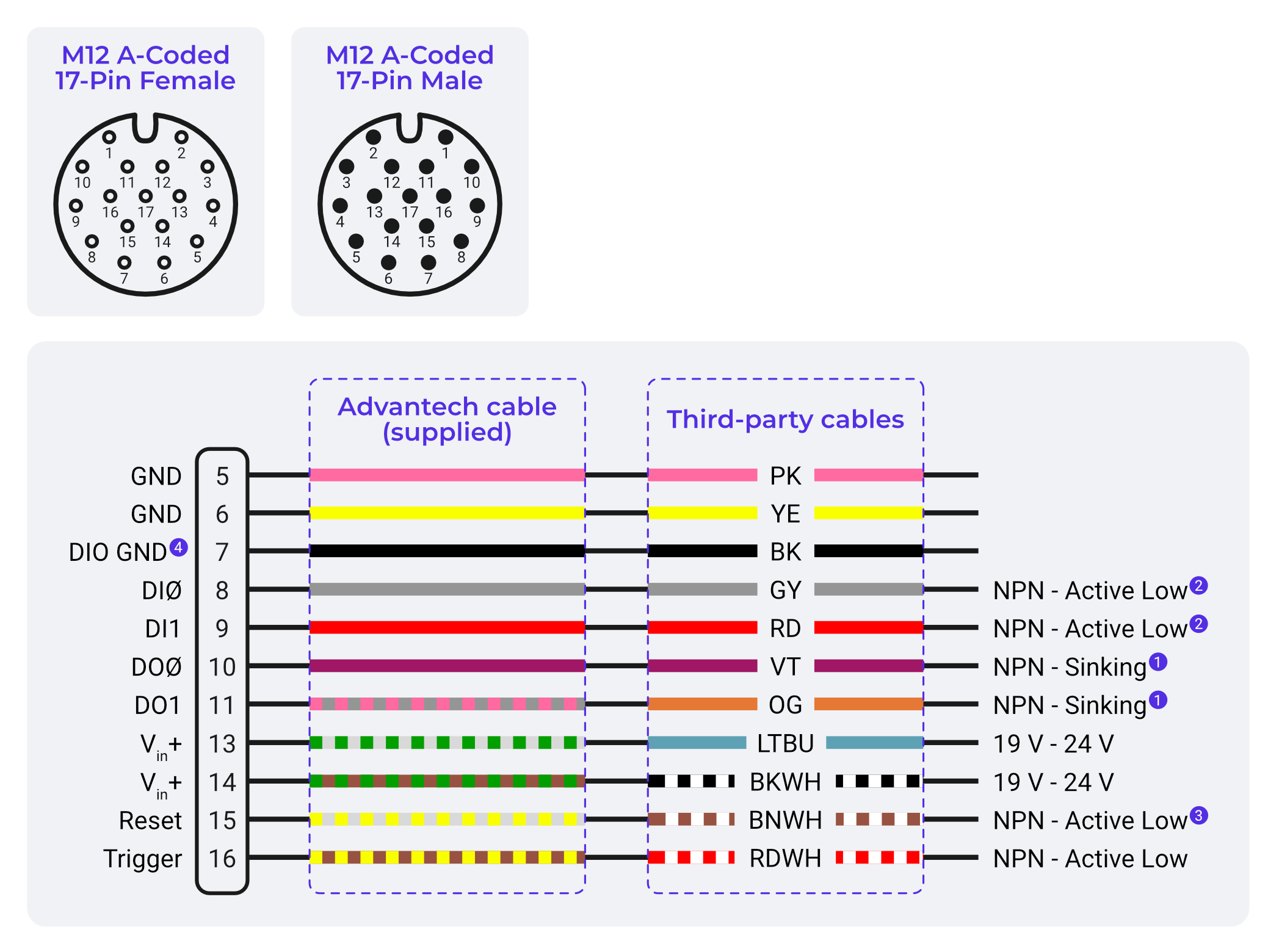
M12 A-Coded 17-Pin – Power & I/O Connector
The OV20i uses a male M12 17-pin connector for power, digital I/O, and reset functionality.
Pin Layout
| Pin | Signal Name | Function |
|---|---|---|
| 5, 6 | Power GND | 0V return path |
| 7 | DIO GND | Ground return for digital I/O |
| 8 | Digital Input 0 | NPN logic input |
| 9 | Digital Input 1 | NPN logic input |
| 10 | Digital Output 0 | NPN open collector |
| 11 | Digital Output 1 | NPN open collector |
| 12 | RS232 RX (optional) | Not used in standard configuration |
| 13, 14 | Power VIN (+24 VDC) | Primary power supply input |
| 15 | Reset Input | Pull low to reboot |
| 16 | Trigger Input | NPN trigger or dry contact |
| Others | Reserved / NC | Not electrically connected |
note
Pins 5, 6, 13, and 14 are required for powering the device.
M12 X-Coded Ethernet Connector
This 8-pin connector supports Gigabit Ethernet.
| Pin | Signal | Function |
|---|---|---|
| 1 | TD+ | Transmit Data (+) |
| 2 | RD+ | Receive Data (+) |
| 3 | TD– | Transmit Data (–) |
| 4 | RD– | Receive Data (–) |
| 5–8 | Bi-Directional | Gigabit pairs |
note
Use an X-coded M12 Ethernet cable for connectivity.
Digital I/O Electrical Summary
| Type | Logic | Trigger Method | Current Limit |
|---|---|---|---|
| Trigger Input | NPN-compatible | Pull to GND | – |
| Digital Inputs | NPN-compatible | Pull to GND | – |
| Digital Outputs | NPN Open Collector | Pulls to GND when active | 100 mA per line |
note
Always tie DIO GND (Pin 7) to your system or PLC ground.
Best Practices
- ✅ Use M12 screw-lock cables rated for industrial use
- ✅ Verify wiring polarity before powering up
- ✅ Add ferrules or strain reliefs in control panels
- ❌ Never hot-swap the M12 Power/I/O connector